10. Services Configuration
The Services section of the GUI allows you to configure, start, and stop the various services that ship with the TrueNAS® system. TrueNAS® supports the following built-in services:
This section demonstrates how to start a TrueNAS® service then describes the available configuration options for each TrueNAS® service.
10.1. Control Services
Services –> Control Services, shown in Figure 10.1a, allows you to quickly determine which services are currently running, to start and stop services, and to configure services. By default, all services (except for the S.M.A.R.T. service) are off until you start them.
A service is stopped if its icon is a red “OFF”. A service is running if its icon is a blue ON. To start or stop a service, click its “ON/OFF” icon.
To configure a service, click the wrench icon associated with the service or click the name of the service in the Services section of the tree menu.
If a service does not start, go to System –> Settings –> Advanced and check the box “Show console messages in the footer”. Console messages will now show at the bottom of your browser. If you click the console messages area, it will pop-up as a window, allowing you to scroll through the output and to copy messages. Watch these messages for errors when you stop and start the problematic service.
If you would like to read the system logs to get more information about a service failure, open `Shell`_ and type more /var/log/messages.
Figure 10.1a: Control Services

10.2. AFP
The Apple Filing Protocol (AFP) is a network protocol that offers file services for Mac computers. Before configuring this service, you should first create your AFP Shares in Sharing –> Apple (AFP) Shares –> Add Apple (AFP) Share. After configuring this service, go to Services –> Control Services to start the service. The AFP shares will not be available on the network if this service is not running.
Starting this service will open the following ports on the TrueNAS® system:
- TCP 548 (afpd)
- TCP 4799 (cnid_metadata)
- UDP 5353 and a random UDP port (avahi)
Figure 10.2a shows the configuration options which are described in Table 10.2a.
Figure 10.2a: AFP Configuration
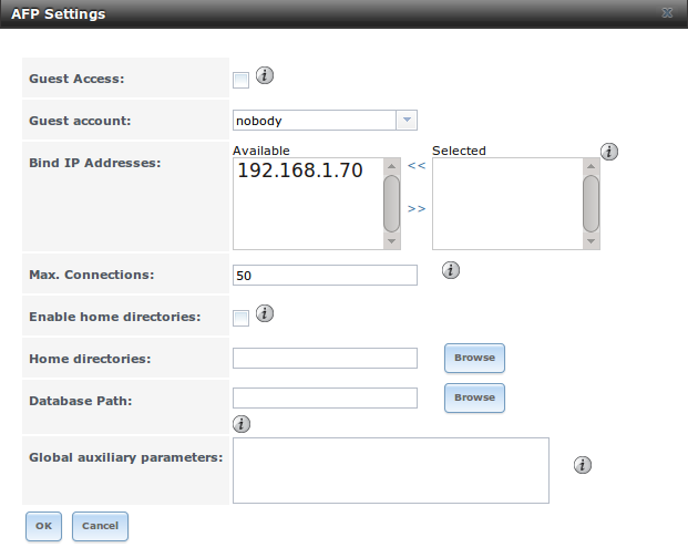
Table 10.2a: AFP Configuration Options
| Setting | Value | Description |
|---|---|---|
| Guest Access | checkbox | if checked, clients will not be prompted to authenticate before accessing the AFP share |
| Guest Account | drop-down menu | select account to use for guest access; the selected account must have permissions to the volume/dataset being shared |
| Max Connections | integer | maximum number of simultaneous connections |
| Enable home directories | checkbox | if checked, any user home directories located under “Home directories” will be available over the share |
| Home directories | Browse button | select the volume or dataset which contains user home directories |
| Database Path | string | specify the path to store the CNID databases used by AFP (default is the root of the volume); the path must be writable |
When configuring home directories, it is recommended to create a dataset to hold the home directories which contains a child dataset for each user. As an example, create a dataset named volume1/homedirs and browse to this dataset when configuring the “Home directories” field of the AFP service. Then, as you create each user, first create a child dataset for that user. For example, create a dataset named volume1/homedirs/user1. When you create the user1 user, browse to the volume1/homedirs/user1 dataset in the “Home Directory” field of the “Add New User” screen.
10.2.1. Troubleshooting
If you receive a “Something wrong with the volume’s CNID DB” error message, run the following command from `Shell`_, replacing the path to the problematic AFP share:
dbd -rf /path/to/share
This command may take a while, depending upon the size of the volume or dataset being shared. This command will wipe the CNID database and rebuild it from the CNIIDs stored in the AppleDouble files.
10.3. CIFS
The Common Internet File System (CIFS) is a network protocol that offers file services for (typically) Windows computers. Unix-like systems that provide a CIFS client can also connect to CIFS shares. Before configuring this service, you should first create your CIFS shares in Sharing –> Windows (CIFS) Shares –> Add Windows (CIFS) Share. After configuring this service, go to Services –> Control Services to start the service. The CIFS shares will not be available on the network if this service is not running.
Note
after starting the CIFS service, it may take several minutes for the master browser election to occur and for the TrueNAS® system to become available in Windows Explorer.
Starting this service will open the following ports on the TrueNAS® system:
- TCP 139 (smbd)
- TCP 445 (smbd)
- UDP 137 (nmbd)
- UDP 138 (nmbd)
Figure 10.3a shows the configuration options which are described in Table 10.3a. This configuration screen is really a front-end to smb4.conf.
Figure 10.3a: Configuring CIFS
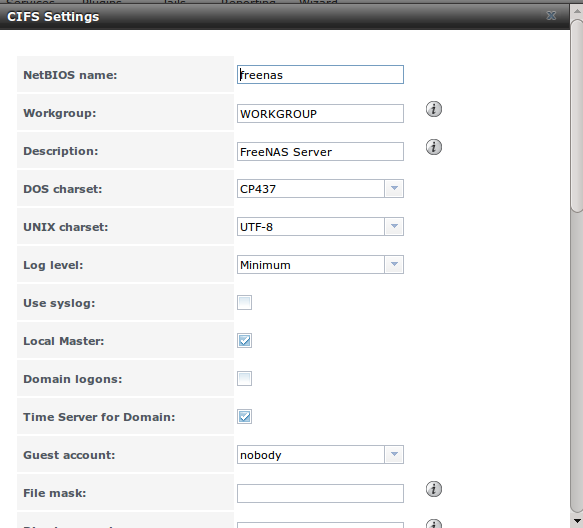
Table 10.3a: CIFS Configuration Options
Table 10.3b: Description of SMB Protocol Versions
| Value | Description |
|---|---|
| CORE | used by DOS |
| COREPLUS | used by DOS |
| LANMAN1 | used by Windows for Workgroups, OS/2, and Windows 9x |
| LANMAN2 | used by Windows for Workgroups, OS/2, and Windows 9x |
| NT1 | used by Windows NT |
| SMB2 | used by Windows 7; same as “SMB2_10” |
| SMB2_02 | used by Windows Vista |
| SMB2_10 | used by Windows 7 |
| SMB2_22 | used by early Windows 8 |
| SMB2_24 | used by Windows 8 beta |
| SMB3 | used by Windows 8 |
| SMB3_00 | used by Windows 8, mostly the same as “SMB2_24” |
Note
Windows 8.1 and Windows Server 2012 R2 use SMB3.02 which is not yet supported by Samba.
10.3.1. Troubleshooting Tips
Windows automatically caches file sharing information. If you make changes to a CIFS share or to the permissions of a volume/dataset being shared by CIFS and are no longer able to access the share, try logging out and back into the Windows system. Alternately, users can type net use /delete from the command line to clear their SMB sessions.
Windows also automatically caches login information. If you wish users to be prompted to login every time access is required, reduce the cache settings on the client computers.
Where possible, avoid using a mix of case in filenames as this may cause confusion for Windows users. Representing and resolving filenames with Samba explains this in more detail.
If permissions work for Windows users but not for OS X users, try disabling “Unix Extensions” and restarting the CIFS service.
If the CIFS service will not start, run this command from `Shell`_ to see if there is an error in the configuration:
testparm /usr/local/etc/smb4.conf**
If clients have problems connecting to the CIFS share, go to Services –> CIFS and verify that “Server maximum protocol” is set to “SMB2”.
It is recommended to use a dataset for CIFS sharing. When creating the dataset, make sure that the “Share type” is set to Windows.
Warning
Do not use chmod to attempt to fix the permissions on a CIFS share as it destroys the Windows ACLs. The correct way to manage permissions on a CIFS share is to manage the share security from a Windows system as either the owner of the share or a member of the group the share is owned by. To do so, right-click on the share, click “Properties” and navigate to the “Security” tab. If you already destroyed the ACLs using chmod, winacl can be used to fix them. Type winacl from `Shell`_ for usage instructions.
10.4. Directory Services
TrueNAS® supports the following directory services:
- Active Directory (for Windows 2000 and higher networks)
- Domain Controller (for configuring TrueNAS® as a domain controller)
- LDAP
- NIS
- NT4 (for Windows networks older than Windows 2000)
This section summarizes each of these services and their available configurations within the TrueNAS® GUI.
Note
at this time, only one directory service can be configured. That service must first be selected in the System –> Settings –> General –> Directory Service drop-down menu. Once selected, a Directory Service entry will be added to Services –> Control Services so that the service can be started, stopped, and configured.
10.4.1. Active Directory
Active Directory (AD) is a service for sharing resources in a Windows network. AD can be configured on a Windows server that is running Windows Server 2000 or higher or on a Unix-like operating system that is running Samba version 4. Since AD provides authentication and authorization services for the users in a network, you do not have to recreate these user accounts on the TrueNAS® system. Instead, configure the Active Directory service so that it can import the account information and imported users can be authorized to access the CIFS shares on the TrueNAS® system.
Note
if your network contains an NT4 domain controller, or any domain controller containing a version which is earlier than Windows 2000, configure NT4 instead.
Before configuring the Active Directory service, ensure name resolution is properly configured by :command:`ping`ing the domain name of the Active Directory domain controller from `Shell`_ on the TrueNAS® system. If the ping fails, check the DNS server and default gateway settings in Network –> Global Configuration on the TrueNAS® system.
Next, add a DNS record for the TrueNAS® system on the Windows server and verify that you can ping the hostname of the TrueNAS® system from the domain controller.
Active Directory relies on Kerberos, which is a time sensitive protocol. This means that the time on both the TrueNAS® system and the Active Directory Domain Controller can not be out of sync by more than a few minutes. The best way to ensure that the same time is running on both systems is to configure both systems to:
- use the same NTP server (set in System –> NTP Servers on the TrueNAS® system)
- have the same timezone
- be set to either localtime or universal time at the BIOS level
Figure 10.4a shows the screen that appears when you click Services –> Directory Services –> Active Directory. Table 10.4a describes the configurable options. Some settings are only available in “Advanced Mode”. To see these settings, either click the “Advanced Mode” button or configure the system to always display these settings by checking the box “Show advanced fields by default” in System –> Settings –> Advanced.
Figure 10.4a: Configuring Active Directory

Table 10.4a: Active Directory Configuration Options
Note
Active Directory places restrictions on which characters are allowed in Domain and NetBIOS names. If you are having problems connecting to the realm, verify that your settings do not include any disallowed characters. Also, the Administrator Password cannot contain the $ character. If a $ exists in the domain administrator’s password, kinit will report a “Password Incorrect” error and ldap_bind will report an “Invalid credentials (49)” error.
Once you have configured the Active Directory service, start it in Services –> Control Services –> Directory Services. It may take a few minutes for the Active Directory information to be populated to the TrueNAS® system. Once populated, the AD users and groups will be available in the drop-down menus of the permissions screen of a volume/dataset. For performance reasons, every available user may not show in the listing. However, it will autocomplete all applicable users if you start typing in a username.
You can verify which Active Directory users and groups have been imported to the TrueNAS® system by using these commands within the TrueNAS® `Shell`_:
wbinfo -u
(to view users)
- ::
- wbinfo -g
(to view groups)
In addition, wbinfo -t will test the connection and, if successful, will give a message similar to:
checking the trust secret for domain YOURDOMAIN via RPC calls succeeded
To manually check that a specified user can authenticate:
net ads join -S dcname -U username
If no users or groups are listed in the output of those commands, these commands will provide more troubleshooting information:
getent passwd

getent group
10.4.1.1. Using a Keytab
Kerberos keytabs are used to do Active Directory joins without a password. This means that the password for the Active Directory administrator account does not need to be saved into the TrueNAS® configuration database, which is a security risk in some environments.
When using a keytab, it is recommended to create and use a less privileged account for performing the required LDAP queries as the password for that account will be stored in the TrueNAS® configuration database. Create this account on the domain controller, then input that account name and its associated password into the “Domain Account Name” and “Domain Account Password” fields in the screen shown in Figure 10.4a.
The keytab itself can be created on a Windows system using these commands. The text in red needs to be modified to the actual values used in the domain.:
ktpass.exe -out hostname.keytab host/hostname@DOMAINNAME -ptype KRB5_NT_PRINCIPAL -mapuser DOMAIN\username -pass userpass

setspn -A host/hostname@DOMAINNAME DOMAIN\username
where:
- hostname is the fully qualified hostname of the domain controller
- DOMAINNAME is the domain name in all caps
- DOMAIN is the pre-Windows 2000 short name for the domain
- username is the privileged account name
- userpass is the password associated with username
This will create a keytab with sufficient privileges to grant tickets for CIFS and LDAP.
Once the keytab is generated, transfer it to the TrueNAS® system, check the “Use keytab” box and browse to the location of the keytab.
10.4.1.2. Troubleshooting Tips
If you are running AD in a 2003/2008 mixed domain, see this forum post for instructions on how to prevent the secure channel key from becoming corrupt.
Active Directory uses DNS to determine the location of the domain controllers and global catalog servers in the network. Use the host -t srv _ldap._tcp.domainname.com command to determine the network’s SRV records and, if necessary, change the weight and/or priority of the SRV record to reflect the fastest server. More information about SRV records can be found in the Technet article How DNS Support for Active Directory Works.
The realm that is used depends upon the priority in the SRV DNS record, meaning that DNS can override your Active Directory settings. If you are unable to connect to the correct realm, check the SRV records on the DNS server. This article describes how to configure KDC discovery over DNS and provides some examples of records with differing priorities.
If the cache becomes out of sync due to an AD server being taken off and back online, resync the cache using System –> Settings –> Advanced –> Rebuild LDAP/AD Cache.
An expired password for the administrator account will cause kinit to fail so ensure that the password is still valid.
Try creating a Computer entry on the Windows server’s OU. When creating this entry, enter the TrueNAS® hostname in the name field. Make sure it is the same name as the one set in the “Hostname” field in Network –> Global Configuration and the “NetBIOS Name” in Services –> Directory Services –> Active Directory settings. Make sure the hostname of the domain controller is set in the “Domain Controller” field of Services –> Directory Services –> Active Directory.
10.4.2. Domain Controller
Beginning with TrueNAS® 9.2.1, TrueNAS® uses Samba4, meaning that it can be configured to act as the domain controller for a network. Refer to the Samba FAQ for further information.
Note
creating a domain controller is a complex process that requires a good understanding of how Active Directory works. While TrueNAS® makes it easy to input the needed settings into the administrative graphical interface, it can’t tell you what those settings should be. Refer to the Samba AD DC HOWTO for more information about creating a new domain. The current implementation does not support a configuration that allows TrueNAS® to join an existing domain as a domain controller.
Figure 10.4b shows the configuration screen for creating a domain controller and Table 10.4b summarizes the available options.
Figure 10.4b: Domain Controller Settings

Table 10.4b: Domain Controller Configuration Options
| Setting | Value | Description |
|---|---|---|
| Realm | string | capitalized DNS realm name |
| Domain | string | capitalized domain name |
| Server Role | drop-down menu | at this time, the only supported role is as the domain controller for a new domain |
| DNS Backend | drop-down menu | choices are SAMBA_INTERNAL, BIND9_FLATFILE, BIND9_DLZ, or NONE; refer to Which DNS backend should I choose? for details |
| DNS Forwarder | string | IP address of DNS forwarder; required for recursive queries when SAMBA_INTERNAL is selected |
| Domain Forest Level | drop-down menu | choices are 2000, 2003, 2008, or 2008_R2; refer to Understanding Active Directory Domain Services (AD DS) Functional Levels for details |
| Administrator password | string | password to be used for the Active Directory administrator account |
10.4.3. LDAP
TrueNAS® includes an OpenLDAP client for accessing information from an LDAP server. An LDAP server provides directory services for finding network resources such as users and their associated permissions. Examples of LDAP servers include Microsoft Server (2000 and newer), Mac OS X Server, Novell eDirectory, and OpenLDAP running on a BSD or Linux system. If an LDAP server is running on your network, you should configure the TrueNAS® LDAP service so that the network’s users can authenticate to the LDAP server and thus be provided authorized access to the data stored on the TrueNAS® system.
Note
LDAP will not work with CIFS shares until the LDAP directory has been configured for and populated with Samba attributes. The most popular script for performing this task is smbldap-tools and instructions for using it can be found at The Linux Samba-OpenLDAP Howto.
Figure 10.4c shows the LDAP Configuration screen that is seen when you click Services –> Directory Services –> LDAP.
Table 10.4c summarizes the available configuration options. If you are new to LDAP terminology, skim through the OpenLDAP Software 2.4 Administrator’s Guide.
Figure 10.4c: Configuring LDAP

Table 10.4c: LDAP Configuration Options
| Setting | Value | Description |
|---|---|---|
| Hostname | string | hostname or IP address of LDAP server |
| Base DN | string | top level of the LDAP directory tree to be used when searching for resources (e.g. dc=test,dc=org) |
| Allow Anonymous Binding | checkbox | instructs LDAP server to not provide authentication and to allow read/write access to any client |
| Root bind DN | string | name of administrative account on LDAP server (e.g. cn=Manager,dc=test,dc=org) |
| Root bind password | string | password for “Root bind DN” |
| Password Encryption | drop-down menu | select a type supported by the LDAP server, choices are: clear (unencrypted), crypt, md5, nds, racf, ad, or exop |
| User Suffix | string | optional, can be added to name when user account added to LDAP directory (e.g. dept. or company name) |
| Group Suffix | string | optional, can be added to name when group added to LDAP directory (e.g. dept. or company name) |
| Password Suffix | string | optional, can be added to password when password added to LDAP directory |
| Machine Suffix | string | optional, can be added to name when system added to LDAP directory (e.g. server, accounting) |
| Encryption Mode | drop-down menu | choices are Off, SSL, or TLS |
| Self signed certificate | string | used to verify the certificate of the LDAP server if SSL connections are used; paste the output of the command openssl s_client -connect server:port -showcerts |
| Auxiliary Parameters | string | ldap.conf(5) options, one per line, not covered by other options in this screen |
Note
TrueNAS® automatically appends the root DN. This means that you should not include the scope and root DN when configuring the user, group, password, and machine suffixes.
After configuring the LDAP service, start it in Services –> Control Services –> Directory Services. If the service will not start, refer to the Common errors encountered when using OpenLDAP Software for common errors and how to fix them. When troubleshooting LDAP, open `Shell`_ and look for error messages in /var/log/auth.log.
To verify that the users have been imported, type getent passwd from `Shell`_. To verify that the groups have been imported, type getent group.
10.4.4. NIS
Network Information Service (NIS) is a service which maintains and distributes a central directory of Unix user and group information, hostnames, email aliases and other text-based tables of information. If a NIS server is running on your network, the TrueNAS® system can be configured to import the users and groups from the NIS directory.
After configuring this service, start it in Services –> Control Services –> Directory Services.
Figure 10.4d shows the configuration screen which opens when you click Services –> Directory Services –> NIS. Table 10.4d summarizes the configuration options.
Figure 10.4d: NIS Configuration

Table 10.4d: NIS Configuration Options
10.4.5. NT4
This service should only be configured if the Windows network’s domain controller is running NT4. If it is not, you should configure Active Directory instead.
Figure 10.4e shows the configuration screen that appears when you click Services –> Directory Services –> NT4. These options are summarized in Table 10.4e.
After configuring the NT4 service, start it in Services –> Control Services –> Directory Services.
Figure 10.4e: NT4 Configuration Options

Table 10.4e: NT4 Configuration Options
| Setting | Value | Description |
|---|---|---|
| Domain Controller | string | hostname of domain controller |
| NetBIOS Name | string | hostname of TrueNAS® system |
| Workgroup Name | string | name of Windows server’s workgroup |
| Administrator Name | string | name of the domain administrator account |
| Administrator Password | string | input and confirm the password for the domain administrator account |
10.5. Dynamic DNS
Dynamic DNS (DDNS) is useful if your TrueNAS® system is connected to an ISP that periodically changes the IP address of the system. With dynamic DNS, the system can automatically associate its current IP address with a domain name, allowing you to access the TrueNAS® system even if the IP address changes. DDNS requires you to register with a DDNS service such as DynDNS.
Figure 10.5a shows the DDNS configuration screen and Table 10.5a summarizes the configuration options. The values you need to input will be given to you by the DDNS provider. After configuring DDNS, don’t forget to start the DDNS service in Services –> Control Services.
Figure 10.5a: Configuring DDNS
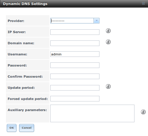
Table 10.5a: DDNS Configuration Options
| Setting | Value | Description |
|---|---|---|
| Provider | drop-down menu | several providers are supported; if your provider is not listed, leave this field blank and specify the custom provider in the “Auxiliary parameters” field |
| Domain name | string | fully qualified domain name (e.g. yourname.dyndns.org) |
| Username | string | username used to logon to the provider and update the record |
| Password | string | password used to logon to the provider and update the record |
| Update period | integer | in seconds; be careful with this setting as the provider may block you for abuse if this setting occurs more often than the IP address changes |
| Forced update period | integer | in seconds so be careful with this setting as the provider may block you for abuse; issues a DDNS update request even when the address has not changed so that the service provider knows that the account is still active |
| Auxiliary parameters | string | additional parameters passed to the provider during record update; an example of specifying a custom provider is dyndns_system default@provider.com |
10.6. FTP
TrueNAS® uses the proftpd FTP server to provide FTP services. Once the FTP service is configured and started, clients can browse and download data using a web browser or FTP client software. The advantage of FTP is that easy-to-use cross-platform utilities are available to manage uploads to and downloads from the TrueNAS® system. The disadvantage of FTP is that it is considered to be an insecure protocol, meaning that it should not be used to transfer sensitive files. If you are concerned about sensitive data, see Encrypting FTP.
This section provides an overview of the FTP configuration options. It then provides examples for configuring anonymous FTP, specified user access within a chroot environment, encrypting FTP connections, and troubleshooting tips.
10.6.1. FTP Configuration Options
Figure 10.6a shows the configuration screen for Services –> FTP. Some settings are only available in “Advanced Mode”. To see these settings, either click the “Advanced Mode” button or configure the system to always display these settings by checking the box “Show advanced fields by default” in System –> Settings –> Advanced.
Figure 10.6a: Configuring FTP

Table 10.6a summarizes the available options when configuring the FTP server:
Table 10.6a: FTP Configuration Options
The following example demonstrates the auxiliary parameters that will prevent all users from performing the FTP DELETE command:
<Limit DELE>
DenyAll
</Limit>
10.6.2. Anonymous FTP
Anonymous FTP may be appropriate for a small network where the TrueNAS® system is not accessible from the Internet and everyone in your internal network needs easy access to the stored data. Anonymous FTP does not require you to create a user account for every user. In addition, passwords are not required so you don’t have to manage changed passwords on the TrueNAS® system.
To configure anonymous FTP:
- Give the built-in ftp user account permissions to the volume/dataset to be shared in Storage –> Volumes as follows:
- Owner(user): select the built-in ftp user from the drop-down menu
- Owner(group): select the built-in ftp group from the drop-down menu
- Mode: review that the permissions are appropriate for the share
Note
for FTP, the type of client does not matter when it comes to the type of ACL. This means that you always use Unix ACLs, even if Windows clients will be accessing TrueNAS® via FTP.
- Configure anonymous FTP in Services –> FTP by setting the following attributes:
- check the box “Allow Anonymous Login”
- Path: browse to the volume/dataset/directory to be shared
- Start the FTP service in Services -> Control Services. Click the red “OFF” button next to FTP. After a second or so, it will change to a blue ON, indicating that the service has been enabled.
- Test the connection from a client using a utility such as Filezilla.
In the example shown in Figure 10.6b, a user has input the following information into the Filezilla client:
- IP address of the TrueNAS® server: 192.168.1.113
- Username: anonymous
- Password: the email address of the user
Figure 10.6b: Connecting Using Filezilla
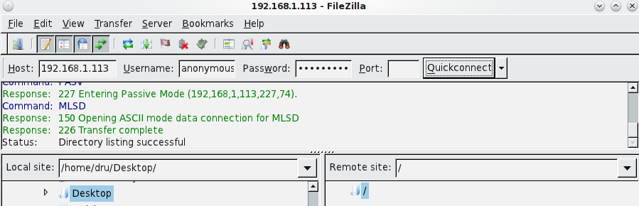
The messages within the client indicate that the FTP connection is successful. The user can now navigate the contents of the root folder on the remote site–this is the volume/dataset that was specified in the FTP service configuration. The user can also transfer files between the local site (their system) and the remote site (the TrueNAS® system).
10.6.3. Specified User Access in chroot
If you require your users to authenticate before accessing the data on the TrueNAS® system, you will need to either create a user account for each user or import existing user accounts using Active Directory or LDAP. If you then create a ZFS dataset for each user, you can chroot each user so that they are limited to the contents of their own home directory. Datasets provide the added benefit of configuring a quota so that the size of the user’s home directory is limited to the size of the quota.
To configure this scenario:
- Create a ZFS dataset for each user in Storage –> Volumes. Click an existing ZFS volume –> Create ZFS Dataset and set an appropriate quota for each dataset. Repeat this process to create a dataset for every user that will need access to the FTP service.
- If you are not using AD or LDAP, create a user account for each user in Account –> Users –> Add User. For each user, browse to the dataset created for that user in the “Home Directory” field. Repeat this process to create a user account for every user that will need access to the FTP service, making sure to assign each user their own dataset.
- Set the permissions for each dataset in Storage –> Volumes. Click the “Change Permissions” button for a dataset to assign a user account as “Owner” of that dataset and to set the desired permissions for that user. Repeat for each dataset.
Note
for FTP, the type of client does not matter when it comes to the type of ACL. This means that you always use Unix ACLs, even if Windows clients will be accessing TrueNAS® via FTP.
- Configure FTP in Services –> FTP with the following attributes:
- Path: browse to the parent volume containing the datasets
- make sure the boxes for “Allow Anonymous Login” and “Allow Root Login” are unchecked
- check the box “Allow Local User Login”
- check the box “Always Chroot”
- Start the FTP service in Services -> Control Services. Click the red “OFF” button next to FTP. After a second or so, it will change to a blue ON, indicating that the service has been enabled.
- Test the connection from a client using a utility such as Filezilla.
To test this configuration in Filezilla, use the “IP address” of the TrueNAS® system, the “Username” of a user that has been associated with a dataset, and the “Password” for that user. The messages should indicate that the authorization and the FTP connection are successful. The user can now navigate the contents of the root folder on the remote site–this time it is not the entire volume but the dataset that was created for that user. The user should be able to transfer files between the local site (their system) and the remote site (their dataset on the TrueNAS® system).
10.6.4. Encrypting FTP
To configure any FTP scenario to use encrypted connections:
- Enable TLS in Services –> FTP. Check the box “Enable TLS”. Once you press “OK”, a certificate and key will automatically be generated for you and proftpd will restart and be configured to use that certificate. If you prefer to use your own certificate, delete the automatically generated one that appears in the “Certificate and private key field” and paste in your own certificate and key.
- Specify secure FTP when accessing the TrueNAS® system. For example, in Filezilla input ftps://IP_address (for an implicit connection) or ftpes://IP_address (for an explicit connection) as the “Host” when connecting. The first time a user connects, they should be presented with the certificate of the TrueNAS® system. Click “OK” to accept the certificate and negotiate an encrypted connection.
To force encrypted connections, add the following line to “Auxiliary Parameters”:
TLS Required on
10.6.5. Troubleshooting
The FTP service will not start if it can not resolve the system’s hostname to an IP address using DNS. To see if the FTP service is running, open `Shell`_ and issue the command:
sockstat -4p 21*
If there is nothing listening on port 21, proftpd isn’t running. To see the error message that occurs when TrueNAS® tries to start the FTP service, go to System –> Settings –> Advanced, check the box “Show console messages in the footer” and click “Save”. Next, go to Services –> Control Services and switch the FTP service off then back on in the GUI. Watch the console messages at the bottom of the browser for errors.
If the error refers to DNS, either create an entry in your local DNS server with the TrueNAS® system’s hostname and IP address or add an entry for the IP address of the TrueNAS® system in the “Host name database” field of Network –> Global Configuration`.
10.7. iSCSI
iSCSI is a protocol standard for the consolidation of storage data. iSCSI allows TrueNAS® to act like a storage area network (SAN) over an existing Ethernet network. Specifically, it exports disk devices over an Ethernet network that iSCSI clients (called initiators) can attach to and mount. Traditional SANs operate over fibre channel networks which require a fibre channel infrastructure such as fibre channel HBAs, fibre channel switches, and discrete cabling. iSCSI can be used over an existing Ethernet network, although dedicated networks can be built for iSCSI traffic in an effort to boost performance. iSCSI also provides an advantage in an environment that uses Windows shell programs; these programs tend to filter “Network Location” but iSCSI mounts are not filtered. TrueNAS® uses istgt to provide iSCSI.
Before configuring the iSCSI service, you should be familiar with the following iSCSI terminology:
CHAP: an authentication method which uses a shared secret and three-way authentication to determine if a system is authorized to access the storage device and to periodically confirm that the session has not been hijacked by another system. In iSCSI, the initiator (client) performs the CHAP authentication.
Mutual CHAP: a superset of CHAP in that both ends of the communication authenticate to each other.
Initiator: a client which has authorized access to the storage data on the TrueNAS® system. The client requires initiator software to connect to the iSCSI share.
Target: a storage resource on the TrueNAS® system.
Extent: the storage unit to be shared. It can either be a file or a device.
LUN: stands for Logical Unit Number and represents a logical SCSI device. An initiator negotiates with a target to establish connectivity to a LUN; the result is an iSCSI connection that emulates a connection to a SCSI hard disk. Initiators treat iSCSI LUNs the same way as they would a raw SCSI or IDE hard drive; rather than mounting remote directories, initiators format and directly manage filesystems on iSCSI LUNs.
TrueNAS® supports multiple iSCSI drives. When configuring multiple iSCSI LUNs, create a new target for each LUN. Portal groups and initiator groups can be reused without any issue. Since istgt multiplexes a target with multiple LUNs over the same TCP connection, you will experience contention from TCP if there is more than one target per LUN.
In order to configure iSCSI:
- Decide if you will use authentication, and if so, whether it will be CHAP or mutual CHAP. If using authentication, create an authorized access as described in Authorized Accesses.
- Create either a device extent or a file extent, as descried in Adding an Extent to be used as storage.
- Determine which hosts are allowed to connect using iSCSI and create an initiator as described in Initiators.
- Create at least one portal as described in Portals.
- Review the Target Global Configuration parameters.
- Create a target as described in Targets.
- Associate a target with an extent as described in Target/Extents.
- Start the iSCSI service in Services –> Control Services.
The rest of this section describes these steps in more detail.
10.7.1. Authorized Accesses
If you will be using CHAP or mutual CHAP to provide authentication, you must create an authorized access in Services –> ISCSI –> Authorized Accesses –> Add Authorized Access. This screen is shown in Figure 10.7a.
Note
this screen sets login authentication. This is different from discovery authentication which is set in Target Global Configuration.
Table 10.7a summarizes the settings that can be configured when adding an authorized access.
Figure 10.7a: Adding an iSCSI Authorized Access
|100000000000017F00000171394D6770_png|
Table 10.7a: Authorized Access Configuration Settings
Note
CHAP does not work with GlobalSAN initiators on Mac OS X.
As authorized accesses are added, they will be listed under “View Authorized Accesses”. In the example shown in Figure 10.7b, three users (test1, test2, and test3) and two groups (1 and 2) have been created, with group 1 consisting of one CHAP user and group 2 consisting of one mutual CHAP user and one CHAP user. Click an authorized access entry to display its “Edit” and “Delete” buttons.
Figure 10.7b: Viewing Authorized Accesses

10.7.2. Extents
In iSCSI, the target virtualizes something and presents it as a device to the iSCSI client. That something can be a device extent or a file extent:
Device extent: virtualizes an unformatted physical disk, RAID controller, `zvol`_, zvol snapshot, or an existing HAST device.
Virtualizing a single disk is slow as there is no caching but virtualizing a hardware RAID controller has higher performance due to its cache. This type of virtualization does a pass-through to the disk or hardware RAID controller. None of the benefits of ZFS are provided and performance is limited to the capabilities of the disk or controller.
Virtualizing a zvol adds the benefits of ZFS such as its read cache and write cache. Even if the client formats the device extent with a different filesystem, as far as TrueNAS® is concerned, the data benefits from ZFS features such as block checksums and snapshots.
File extent: allows you to export a portion of a ZFS volume. The advantage of a file extent is that you can create multiple exports per volume.
10.7.2.1. Adding an Extent
To add an extent, go to Services –> ISCSI –> Extents –> Add Extent. In the example shown in Figure 10.7c, the device extent is using the export zvol that was previously created from the /mnt/volume1 volume.
Table 10.7b summarizes the settings that can be configured when creating an extent. Note that file extent creation will fail if you do not append the name of the file to be created to the volume/dataset name.
Figure 10.7c: Adding an iSCSI Extent
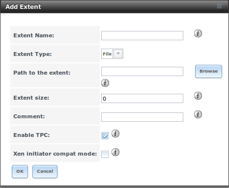
Table 10.7b: Extent Configuration Settings
| Setting | Value | Description |
|---|---|---|
| Extent Name | string | name of extent; if the “Extent size” is not 0, it can not be an existing file within the volume/dataset |
| Extent Type | drop-down menu | select from File or Device |
| Path to the extent | browse button | only appears if “File” is selected; either browse to an existing file and use 0 as the “Extent size”, or browse to the volume or dataset, click the “Close” button, append the “Extent Name” to the path, and specify a value in “Extent size” |
| Device | drop-down menu | only appears if Device is selected; select the unformatted disk, controller, zvol, zvol snapshot, or HAST device |
| Extent size | integer | only appears if File is selected; if the size is specified as 0, the file must already exist and the actual file size will be used; otherwise specifies the size of the file to create |
| Comment | string | optional |
10.7.3. Initiators
The next step is to configure authorized initiators, or the systems which are allowed to connect to the iSCSI targets on the TrueNAS® system. To configure which systems can connect, use Services –> ISCSI –> Initiators –> Add Initiator, shown in Figure 10.7d.
Figure 10.7d: Adding an iSCSI Initiator

Note
TrueNAS® does contain
iscontrol(8). This utility allows the TrueNAS® system to act as an initiator (rather than a target) and must be run from the command line. If you create a custom configuration for iscontrol, back it up as it will not survive a reboot of the system.
Table 10.7c summarizes the settings that can be configured when adding an initiator.
Table 10.7c: Initiator Configuration Settings
| Setting | Value | Description |
|---|---|---|
| Initiators | string | use ALL keyword or a list of initiator hostnames separated by commas with no space |
| Authorized network | string | use ALL keyword or a network address with CIDR mask such as 192.168.2.0/24 |
| Comment | string | optional description |
In the example shown in Figure 10.7e, two groups have been created. Group 1 allows connections from any initiator on any network; Group 2 allows connections from any initiator on the 10.10.1.0/24 network. Click an initiator’s entry to display its “Edit” and “Delete” buttons.
Note
if you delete an initiator, a warning will indicate if any targets or target/extent mappings depend upon the initiator. If you confirm the delete, these will be deleted as well.
Figure 10.7e: Sample iSCSI Initiator Configuration

10.7.4. Portals
A portal specifies the IP address and port number to be used for iSCSI connections. Services –> ISCSI –> Portals –> Add Portal will bring up the screen shown in Figure 10.7f.
Table 10.7d summarizes the settings that can be configured when adding a portal. If you need to assign additional IP addresses to the portal, click the link “Add extra Portal IP”.
Figure 10.7f: Adding an iSCSI Portal
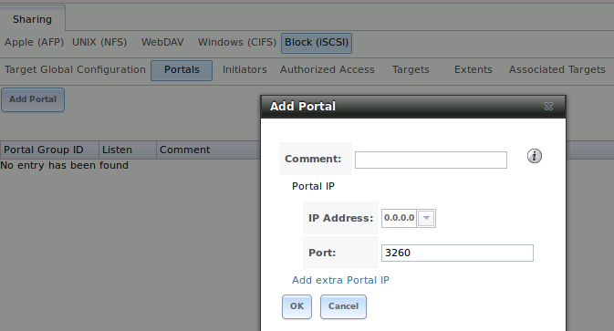
Table 10.7d: Portal Configuration Settings
| Setting | Value | Description |
|---|---|---|
| Comment | string | optional description; portals are automatically assigned a numeric group ID |
| IP address | drop-down menu | select the IP address associated with an interface or the wildcard address of 0.0.0.0 (any interface) |
| Port | integer | TCP port used to access the iSCSI target; default is 3260 |
TrueNAS® systems with multiple IP addresses or interfaces can use a portal to provide services on different interfaces or subnets. This can be used to configure multi-path I/O (MPIO). MPIO is more efficient than a link aggregation.
If the TrueNAS® system has multiple configured interfaces, portals can also be used to provide network access control. For example, consider a system with four interfaces configured with the following addresses:
192.168.1.1/24
192.168.2.1/24
192.168.3.1/24
192.168.4.1/24
You could create a portal containing the first two IP addresses (group ID 1) and a portal containing the remaining two IP addresses (group ID 2). You could then create a target named A with a Portal Group ID of 1 and a second target named B with a Portal Group ID of 2. In this scenario, istgt would listen on all four interfaces, but connections to target A would be limited to the first two networks and connections to target B would be limited to the last two networks.
Another scenario would be to create a portal which includes every IP address except for the one used by a management interface. This would prevent iSCSI connections to the management interface.
10.7.5. Target Global Configuration
Services –> iSCSI –> Target Global Configuration, shown in Figures 10.7g, contains settings that apply to all iSCSI shares. Table 10.7e summarizes the settings that can be configured in the Target Global Configuration screen. The integer values in the table are used to tune network performance; most of these values are described in RFC 3720.
LUC (Logical Unit Controller) is an API provided by istgt to control removable media by providing functions to list targets, load or unload a media to a unit, change media file, or reset a LUN.
In order to dynamically add or remove targets without restarting the iSCSI service, which can disrupt iSCSI initiators, set the following options:
- check the “Enable LUC” box
- leave the “Controller IP address” and “Control Authorized Network” at their default values
- change the “Controller Auth Method” to None
Note
the following operations do require that the iSCSI service be restarted: editing a target, adding or deleting LUNs, or changing the size of an existing extent.
Figure 10.7g: iSCSI Target Global Configuration Variables

Table 10.7e: Target Global Configuration Settings
| Setting | Value | Description |
|---|---|---|
| Base Name | string | see the “Constructing iSCSI names using the iqn. format” section of RFC 3721 if you are unfamiliar with this format |
| Discovery Auth Method | drop-down menu | configures the authentication level required by the target for discovery of valid devices, where None will allow anonymous discovery, CHAP and Mutual CHAP require authentication, and Auto lets the initiator decide the authentication scheme |
| Discovery Auth Group | drop-down menu | depends on “Discovery Auth Method” setting: required if set to CHAP or Mutual CHAP, optional if set to Auto, and not needed if set to None |
| Enable multithreaded mode | checkbox | do not check this box unless instructed to do so by a support engineer |
| I/O Timeout | integer representing seconds | sets the limit on how long an I/O can be outstanding before an error condition is returned; values range from 0-300 with a default of 30 |
| NOPIN Interval | integer representing seconds | how often the target sends a NOP-IN packet to keep a discovered session alive; values range from 0-300 with a default of 20 |
| Max. Sessions | integer | limits the number of sessions the target portal will create/accept from initiator portals; values range from 1-65536 with a default of 16 |
| Max. Connections | integer | the number of connections a single initiator can make to a single target; values range from 1-65536 with a default of 8 |
| Max. pre-send R2T | integer | values range from 1-255 with a default of 32 |
| MaxOutstandingR2T | integer | the maximum number of ready to receive packets (R2Ts) the target can have outstanding for a single iSCSI command, where larger values should yield performance increases until “MaxOutstandingR2T” exceeds the size of the largest “Write I/O” divided by “MaxBurstLength”; values range from 1-255 with a default of 16 |
| First burst length | integer | maximum amount in bytes of unsolicited data an iSCSI initiator may send to the target during the execution of a single SCSI command; values range from 1- 2^32 with a default of 65,536 |
| Max burst length | integer | maximum write size in bytes the target is willing to receive between R2Ts; values range from 1-2^32 with a default of 262,144 |
| Max receive data segment length | integer | in bytes; values range from 1-2^32 with a default of 262,144 |
| DefaultTime2Wait | integer | minimum time in seconds to wait before attempting a logout or an active task reassignment after an unexpected connection termination or reset; values range from 1-300 with a default of 2 |
| DefaultTime2Retain | integer | maximum time in seconds after “Time2Wait” before which an active task reassignment is still possible after an unexpected connection termination or reset; values range from 1-300 with a default of 60 |
| Enable LUC | checkbox | check if you need to dynamically add and remove targets; if checked, the next three fields are activated and required |
| Controller IP address | IP address | keep the default value of 127.0.0.1 |
| Controller TCP port | integer | possible values range from 1024-65535 with a default value of 3261 |
| Controller Authorized netmask | subnet mask | keep the default value of 127.0.0.0/8 |
| Controller Auth Method | drop-down menu | choices are None, Auto, CHAP, or Mutual CHAP |
| Controller Auth Group | drop-down menu | required if “Controller Auth Method” is set to CHAP or Mutual CHAP, optional if set to Auto, and not needed if set to None |
If the settings in this screen differ from the settings on the initiator, set them to be the same. When making changes, always match the larger setting.
If you are changing integer values to optimize the connection, refer to the iSCSI initiator’s documentation. For example, the following modifications are recommended if the iSCSI initiator is running on Xenserver:
- Max. pre-send R2T: 255
- MaxOutstandingR2T: 64
- First burst length: 262,144
- Max burst length: 2,097,152
10.7.6. Targets
Next, create a Target using Services –> ISCSI –> Targets –> Add Target, as shown in Figure 10.7h. A target combines a “portal ID”, “allowed initiator ID”, and an “authentication method”. Table 10.7f summarizes the settings that can be configured when creating a Target.
Note
an iSCSI target creates a block device that may be accessible to multiple initiators. A clustered filesystem is required on the block device, such as VMFS used by VMWare ESX/ESXi, in order for multiple initiators to mount the block device read/write. If a traditional filesystem such as EXT, XFS, FAT, NTFS, UFS, or ZFS is placed on the block device, care must be taken that only one initiator at a time has read/write access or the result will be filesystem corruption. If you need to support multiple clients to the same data on a non-clustered filesystem, use CIFS or NFS instead of iSCSI or create multiple iSCSI targets (one per client).
Figure 10.7h: Adding an iSCSI Target

Table 10.7f: Target Settings
| Setting | Value | Description |
|---|---|---|
| Target Name | string | required value; base name will be appended automatically if it does not start with iqn |
| Target Alias | string | optional user-friendly name |
| Serial | string | unique ID for target to allow for multiple LUNs; the default is generated from the system’s MAC address |
| Target Flags | drop-down menu | choices are read-write or read-only |
| Portal Group ID | drop-down menu | leave empty or select number of existing portal to use |
| Initiator Group ID | drop-down menu | select which existing initiator group has access to the target |
| Auth Method | drop-down menu | choices are None, Auto, CHAP, or Mutual CHAP |
| Authentication Group number | drop-down menu | None or integer representing number of existing authorized access |
| Queue Depth | integer | see this post for an explanation of the math involved; values are 0-255 where 0 is disabled and default is 32 |
| Logical Block Size | integer | should only be changed to emulate a physical disk’s size or to increase the block size to allow for larger filesystems on an operating system limited by block count; default is 512 |
10.7.7. Target/Extents
The last step is associating an extent to a target within Services –> ISCSI –> Target/Extents –> Add Target/Extent. This screen is shown in Figure 10.7i. Use the drop-down menus to select the existing target and extent.
Figure 10.7i: Associating iSCSI Targets/Extents

Table 10.7g summarizes the settings that can be configured when associating targets and extents.
Table 10.7g: Target/Extents Configuration Settings
| Setting | Value | Description |
|---|---|---|
| Lun ID | drop-down menu | specify the ID of the LUN; the default of Auto will select the next available LUN ID, starting at 0 |
| Target | drop-down menu | select the pre-created target |
| Extent | drop-down menu | select the pre-created extent |
It is recommended to always associate extents to targets in a 1:1 manner, even though the GUI will allow multiple extents to be associated with the same target.
Once iSCSI has been configured, don’t forget to start it in Services –> Control Services. Click the red “OFF” button next to iSCSI. After a second or so, it will change to a blue ON, indicating that the service has started.
10.7.9. Growing LUNs
The method used to grow the size of an existing iSCSI LUN depends on whether the LUN is backed by a file extent or a zvol. Both methods are described in this section.
After the LUN is expanded using one of the methods below, use the tools from the initiator software to grow the partitions and the filesystems it contains.
10.7.9.1. Zvol Based LUN
Before growing a zvol based LUN, make sure that all initiators are disconnected. Stop the iSCSI service in Control Services.
Open `Shell`_ and identify the zvol to be grown:
zfs list -t volume
NAME                   USED    AVAIL   REFER   MOUNTPOINT
tank/iscsi_zvol        4G      17.5G   33.9M   -
Then, grow the zvol. This example grows su`tank/iscsi_zvol from 4G to 6G:
zfs set volsize=6G tank/iscsi_zvol

zfs set refreservation=6G tank/iscsi_zvol
Verify that the changes have taken effect:
zfs list -t volume
NAME                   USED    AVAIL   REFER   MOUNTPOINT
tank/iscsi_zvol        6G      17.5G   33.9M   -
You can now start the iSCSI service and allow initiators to connect.
10.7.9.2. File Extent Based LUN
Before growing a file extent based LUN, make sure that all initiators are disconnected. Stop the iSCSI service in Control Services.
Then, go to Services –> iSCSI –> File Extents –> View File Extents to determine the path of the file extent to grow. Open `Shell`_ to grow the extent. This example grows /mnt/volume1/data by 2G:
truncate -s +2g /mnt/volume1/data
Go back to Services –> iSCSI –> File Extents –> View File Extents and click the “Edit” button for the file extent. Set the size to 0 as this causes the iSCSI target to use the new size of the file.
You can now start the iSCSI service and allow initiators to connect.
10.8. NFS
Network File System (NFS) is a protocol for sharing files on a network. Before configuring this service, you should first create your NFS Shares in Sharing –> Unix (NFS) Shares –> Add Unix (NFS) Share. After configuring this service, go to Services –> Control Panel to start the service.
Starting this service will open the following ports on the TrueNAS® system:
- TCP and UDP 111 (used by rpcbind)
- TCP 2049 (used by nfsd)
Additionally, mountd and rpcbind will each bind to a randomly available UDP port.
Figure 10.8a shows the configuration screen and Table 10.8a summarizes the configuration options for the NFS service.
Figure 10.8a: Configuring NFS
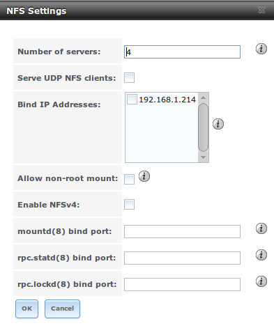
Table 10.8a: NFS Configuration Options
| Setting | Value | Description |
|---|---|---|
| Number of servers | integer | run sysctl -n kern.smp.cpus from `Shell`_ to determine the number; do not exceed the number listed in the output of that command |
| Serve UDP NFS clients | checkbox | check if NFS client needs to use UDP |
| Bind IP Addresses | checkboxes | select the IP address(es) to listen for NFS requests; if left unchecked, NFS will listen on all available addresses |
| Allow non-root mount | checkbox | check this box only if the NFS client requires it |
| mountd(8) bind port | integer | optional; specify port for mountd(8) to bind to |
| rpc.statd(8) bind port | integer | optional; specify port for rpc.statd(8) to bind to |
| rpc.lockd(8) bind port | integer | optional; specify port for rpc.lockd(8) to bind to |
10.9. Rsync
Services –> Rsync is used to configure an rsync server when using rsync module mode. See `Configuring Rsync Module Mode Between Two TrueNAS® Systems`_ for a configuration example.
This section describes the configurable options for the rsyncd service and rsync modules.
Figure 10.9a shows the rsyncd configuration screen which is accessed from Services –> Rsync –> Configure Rsyncd.
Figure 10.9a: Rsyncd Configuration
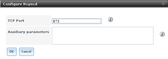
Table 10.9a summarizes the options that can be configured for the rsync daemon:
Table 10.9a: Rsync Configuration Options
| Setting | Value | Description |
|---|---|---|
| TCP Port | integer | port for rsyncd to listen on, default is 873 |
| Auxiliary parameters | string | additional parameters from rsyncd.conf(5) |
10.9.1. Rsync Modules
Figure 10.9b shows the configuration screen that appears when you click Services –> Rsync –> Rsync Modules –> Add Rsync Module.
Table 10.9b summarizes the options that can be configured when creating a rsync module.
Figure 10.9b: Adding an Rsync Module

Table 10.9b: Rsync Module Configuration Options
| Setting | Value | Description |
|---|---|---|
| Module name | string | mandatory; needs to match the setting on the rsync client |
| Comment | string | optional description |
| Path | browse button | volume/dataset to hold received data |
| Access Mode | drop-down menu | choices are Read and Write, Read-only, or Write-only |
| Maximum connections | integer | 0 is unlimited |
| User | drop-down menu | select user that file transfers to and from that module should take place as |
| Group | drop-down menu | select group that file transfers to and from that module should take place as |
| Hosts allow | string | see rsyncd.conf(5) for allowed formats |
| Hosts deny | string | see rsyncd.conf(5) for allowed formats |
| Auxiliary parameters | string | additional parameters from rsyncd.conf(5) |
10.10. S.M.A.R.T.
TrueNAS® uses the smartd(8) service to monitor disk S.M.A.R.T. data for disk health. To fully configure S.M.A.R.T. you need to:
- Schedule when to run the S.M.A.R.T. tests in System –> S.M.A.R.T. Tests –> Add S.M.A.R.T. Test.
- Enable or disable S.M.A.R.T. for each disk member of a volume in Volumes –> View Volumes. By default, this is already enabled on all disks.
- Check the configuration of the S.M.A.R.T. service as described in this section.
- Start the S.M.A.R.T. service in Services –> Control Services.
Figure 10.10a shows the configuration screen that appears when you click Services –> S.M.A.R.T..
Figure 10.10a: S.M.A.R.T Configuration Options

Note
smartd will wake up at every Check Interval configured in Figure 8.10a. It will check the times you configured in your tests to see if any tests should be run. Since the smallest time increment for a test is an hour (60 minutes), it does not make sense to set a check interval value higher than 60 minutes. For example, if you set the check interval for 120 minutes and the smart test to every hour, the test will only be run every 2 hours since the daemon only wakes up every 2 hours.
Table 10.10a summarizes the options in the S.M.A.R.T configuration screen.
Table 10.10a: S.M.A.R.T Configuration Options
| Setting | Value | Description |
|---|---|---|
| Check interval | integer | in minutes, how often to wake up smartd to check to see if any tests have been configured to run |
| Power mode | drop-down menu | the configured test is not performed if the system enters the specified power mode; choices are: Never, Sleep, Standby, or Idle |
| Difference | integer in degrees Celsius | default of 0 disables this check, otherwise reports if the temperature of a drive has changed by N degrees Celsius since last report |
| Informational | integer in degrees Celsius | default of 0 disables this check, otherwise will message with a log level of “LOG_INFO” if the temperature is higher than specified degrees in Celsius |
| Critical | integer in degrees Celsius | default of 0 disables this check, otherwise will message with a log level of “LOG_CRIT” and send an email if the temperature is higher than specified degrees in Celsius |
| Email to report | string | email address of person to receive S.M.A.R.T. alert; separate multiple email recipients with a comma and no space |
10.11. SNMP
SNMP (Simple Network Management Protocol) is used to monitor network-attached devices for conditions that warrant administrative attention. TrueNAS® can be configured as a bsnmpd(8) server using FreeBSD’s simple and extensible SNMP daemon. When you start the SNMP service, the following port will be enabled on the TrueNAS® system:
- UDP 161 (:command:` bsnmpd` listens here for SNMP requests)
Available MIBS are located in /usr/share/SNMP/mibs and /usr/local/share/SNMP/mibs.
Figure 10.11a shows the SNMP configuration screen. Table 10.11a summarizes the configuration options.
Figure 10.11a: Configuring SNMP
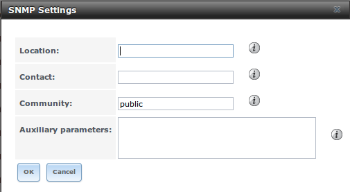
Table 10.11a: SNMP Configuration Options
| Setting | Value | Description |
|---|---|---|
| Location | string | optional description of TrueNAS® system’s location |
| Contact | string | optional email address of TrueNAS® administrator |
| Community | string | password used on the SNMP network, default is public and should be changed for security reasons |
| Auxiliary Parameters | string | additional bsnmpd(8) options not covered in this screen, one per line |
10.12. SSH
Secure Shell (SSH) allows for files to be transferred securely over an encrypted network. If you configure your TrueNAS® system as an SSH server, the users in your network will need to use SSH client software in order to transfer files using SSH.
This section shows the TrueNAS® SSH configuration options, demonstrates an example configuration that restricts users to their home directory, and provides some troubleshooting tips.
10.12.1. SSH Configuration Screen
Figure 10.12a shows the Services –> SSH configuration screen. Once you have configured SSH, don’t forget to start it in Services –> Control Services.
Figure 10.12a: SSH Configuration

Table 10.12a summarizes the configuration options. Some settings are only available in “Advanced Mode”. To see these settings, either click the “Advanced Mode” button or configure the system to always display these settings by checking the box “Show advanced fields by default” in System –> Settings –> Advanced.
Table 10.12a: SSH Configuration Options
| Setting | Value | Description |
|---|---|---|
| TCP Port | integer | port to open for SSH connection requests; 22 by default |
| Login as Root with password | checkbox | for security reasons, root logins are discouraged and disabled by default; if enabled, password must be set for root user in Account –> Users –> View Users |
| Allow Password Authentication | checkbox | if unchecked, key based authentication for all users is required; requires additional setup on both the SSH client and server |
| Allow TCP Port Forwarding | checkbox | allows users to bypass firewall restrictions using SSH’s port forwarding feature |
| Compress Connections | checkbox | may reduce latency over slow networks |
| Host Private Key | string | only available in “Advanced Mode”; allows you to paste a specific host key as the default key is changed with every installation |
| SFTP Log Level | drop-down menu | only available in “Advanced Mode”; select the syslog(3) level of the SFTP server |
| SFTP Log Facility | drop-down menu | only available in “Advanced Mode”; select the syslog(3) facility of the SFTP server |
| Extra Options | string | only available in “Advanced Mode”; additional sshd_config(5) options not covered in this screen, one per line; these options are case-sensitive and mis-spellings may prevent the SSH service from starting |
A few sshd_config(5) options that are useful to input in the “Extra Options” field include:
- ClientAliveInterval: increase this number if ssh connections tend to drop
- ClientMaxStartup: defaults to 10; increase if you have more users
10.12.2. Chrooting Command Line SFTP Users
By default when you configure SSH, users can use the ssh command to login to the TrueNAS® system. A user’s home directory will be the volume/dataset specified in the “Home Directory” field of their user account on the TrueNAS® system. Users can also use the scp and sftp commands to transfer files between their local computer and their home directory on the TrueNAS® system.
While these commands will default to the user’s home directory, users are able to navigate outside of their home directory which can pose a security risk. SSH supports using a chroot to confine users to only the sftp command and to be limited to the contents of their own home directory. To configure this scenario on TrueNAS®, perform the following steps.
Note
some utilities such as WinSCP can bypass the chroot. This section assumes that users are accessing the chroot using the command line sftp.
- Create a ZFS dataset for each user requiring sftp access in Storage –> Volumes.
- If you are not using Active Directory or LDAP, create a user account for each user in Account –> Users –> Add User. In the “Home Directory” field, browse to the location of the dataset you created for that user. Repeat this process to create a user account for every user that will need access to the SSH service.
- Create a group named sftp in Account –> Groups –> Add Group. Then, click on the sftp group in “View Groups” and add the users who are to be restricted to their home directories when using sftp.
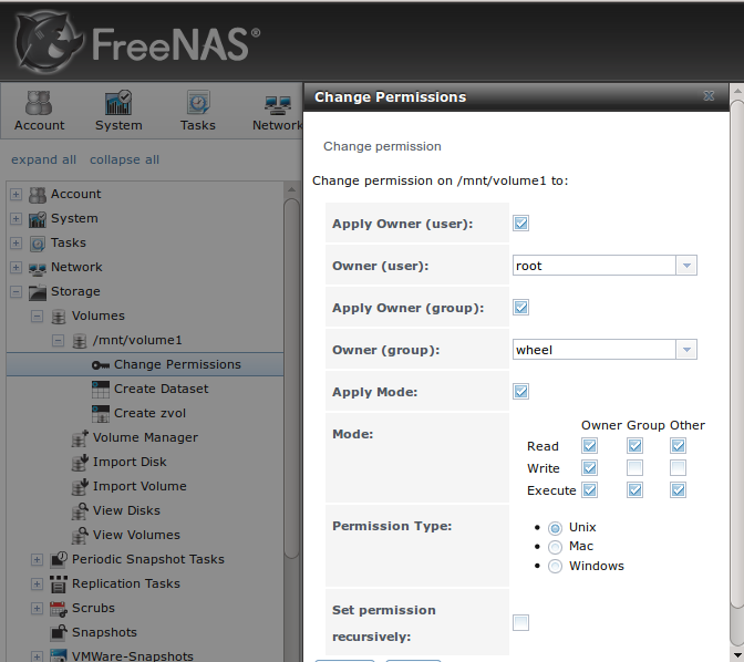
- Set permissions for each dataset in Storage –> Volume –> View Volumes. SSH chroot is very specific with regards to the required permissions (see the ChrootDirectory keyword in sshd_config(5) for details). Your configuration will not work if the permissions on the datasets used by SSH chroot users differ from those shown in Figure 10.12b.**
- Create a home directory within each dataset using `Shell`_. Due to the permissions required by SSH chroot, the user will not have permissions to write to the root of their own dataset until you do this. Since your intention is to limit them to the contents of their home directory, manually create a home directory for each user within their own dataset and change the ownership of the directory to the user. Example 10.12a demonstrates the commands used to create a home directory called user1 for the user account user1 on dataset /mnt/volume1/user1.
Figure 10.12b: Permissions Required by SSH Chroot
Example 10.12a: Creating a User’s Home Directory
mkdir /mnt/volume1/user1/user1

chown user1:user1 /mnt/volume1/user1/user1
#. Configure SSH in Services –> SSH. Add these lines to the “Extra Options” section:
Match Group sftp
ChrootDirectory %h
ForceCommand internal-sftp
AllowTcpForwarding no
- Start the SSH service in Services -> Control Services. Click the red “OFF” button next to SSH. After a second or so, it will change to a blue ON, indicating that the service has been enabled.
- Test the connection from a client by running sftp, ssh, and scp as the user. The sftp command should work but be limited to the user’s home directory and the ssh and scp commands should fail.
10.12.3. Troubleshooting SSH Connections
If you add any “Extra Options” in the SSH configuration screen, be aware that the keywords listed in sshd_config(5) are case sensitive. This means that your configuration will fail to do what you intended if you do not match the upper and lowercase letters of the keyword.
If your clients are receiving “reverse DNS” or timeout errors, add an entry for the IP address of the TrueNAS® system in the “Host name database” field of Network –> Global Configuration.
When configuring SSH, always test your configuration as an SSH user account to ensure that the user is limited to what you have configured and that they have permission to transfer files within the intended directories. If the user account is experiencing problems, the SSH error messages are usually pretty specific to what the problem is. Type the following command within `Shell`_ to read these messages as they occur:
tail -f /var/log/messages
Additional messages regarding authentication errors may be found in /var/log/auth.log.
10.13. TFTP
Trivial File Transfer Protocol (TFTP) is a light-weight version of FTP usually used to transfer configuration or boot files between machines, such as routers, in a local environment. TFTP provides an extremely limited set of commands and provides no authentication.
If the TrueNAS® system will be used to store images and configuration files for the network’s devices, configure and start the TFTP service. Starting the TFTP service will open UDP port 69.
Figure 10.13a shows the TFTP configuration screen and Table 10.13a summarizes the available options.
Figure 10.13a: TFTP Configuration
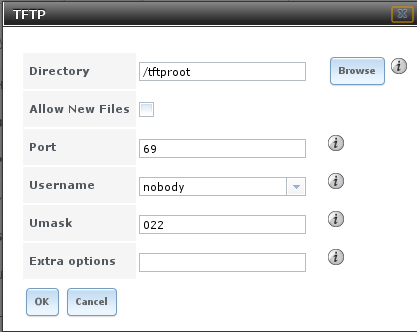
Table 10.13a: TFTP Configuration Options
10.14. UPS
TrueNAS® uses NUT (Network UPS Tools) to provide UPS support. If the TrueNAS® system is connected to a UPS device, configure the UPS service then start it in Services –> Control Services.
Figure 10.14a shows the UPS configuration screen:
Figure 10.14a: UPS Configuration Screen
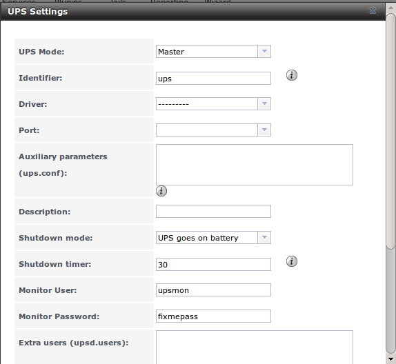
Table 10.14a summarizes the options in the UPS Configuration screen.
Table 10.14a: UPS Configuration Options
| Setting | Value | Description |
|---|---|---|
| UPS Mode | drop-down menu | select from Master or Slave |
| Identifier | string | can contain alphanumeric, period, comma, hyphen, and underscore characters |
| Driver | drop-down menu | supported UPS devices are listed at http://www.networkupstools.org/stable-hcl.html |
| Port | drop-down menu | select the serial or USB port the UPS is plugged into (see NOTE below) |
| Auxiliary Parameters | string | additional options from ups.conf(5) |
| Description | string | optional |
| Shutdown mode | drop-down menu | choices are UPS goes on battery and UPS reaches low battery |
| Shutdown timer | integer | in seconds; will initiate shutdown after this many seconds after UPS enters UPS goes on battery, unless power is restored |
| Monitor User | string | default is upsmon |
| Monitor Password | string | default is known value fixmepass and should be changed; can not contain a space or # |
| Extra users | string | defines the accounts that have administrative access; see upsd.users(5) for examples |
| Remote monitor | checkbox | if enabled, be aware that the default is to listen on all interfaces and to use the known values user upsmon and password fixmepass |
| Send Email Status Updates | checkbox | if checked, activates the “To email” field |
| To email | email address | if “Send Email Status Updates” box checked, email address of person to receive status updates |
| Email subject | string | if “Send Email Status Updates” box checked, subject of email updates |
Note
for USB devices, the easiest way to determine the correct device name is to check the box “Show console messages” in System –> Settings –> Advanced. Plug in the USB device and the console messages will give the name of the /dev/ugenX.X device; where the X’s are the numbers that show on the console.
upsc(8) can be used to get status variables from the UPS daemon such as the current charge and input voltage. It can be run from `Shell`_ using the following syntax. The man page gives some other usage examples.:
upsc ups@localhost
upscmd(8) can be used to send commands directly to the UPS, assuming that the hardware supports the command being sent. Only users with administrative rights can use this command. These users are created in the “Extra users” field.