7. Network Configuration
The Network section of the administrative GUI contains the following components for viewing and configuring the TrueNAS® system’s network settings:
- CARPs:_ used when configuring high availablility.
- Global Configuration: used to to set non-interface specific network settings.
- Interfaces: used to configure a specified interface’s network settings.
- IPMI: provides side-band management should the appliance become unavailable through the graphical administrative interface.
- Link Aggregations: used to configure link aggregation and link failover.
- Network Summary: provides an overview of the current network settings.
- Static Routes: used to add static routes.
- VLANs: used to configure IEEE 802.1q tagging.
Each of these is described in more detail in this section.
7.1. CARPs
Network -> CARPs is used to configure the CARP information that is used when configuring high availability in System -> Failovers.
Failover using CARP is only available on certain appliances and requires an advanced configuration between multiple TrueNAS® appliances that is created with the assistance of an iXsystems support engineer. Failover can only be used with iSCSI or NFS. Contact your iXsystems representative if you wish to schedule a time to configure failover. Do not attempt to configure CARP on your own as it will fail and may render existing shares or volumes inaccessible.
This section provides an overview of CARP terminology and the CARP screen that appears in the graphical administrative utility.
The following terminology is used by CARP:
Redundancy group: a group of hosts on a network segment which are assigned the same virtual IP address. Within the group, one host is designated the “master” and the rest are considered “backups”. The master responds to any traffic directed at the virtual IP address.
Advertisements: the master sends regular network packets known as advertisements so the backups know that it is still available. If the backups don’t receive an advertisement from the master for a set period of time, the backup host with the lowest configured advertisements skew value will take over as master.
Advertisements Skew: measured in 1/256 of a second. The value is added to the advertisement interval in order to make one host advertise a bit slower than the other.
Virtual host ID: allows group members to identify which redundancy group the advertisement belongs to.
Password: in order to prevent a malicious user from spoofing CARP advertisements, each group can be configured with a password.
Figure 7.1a shows the configuration screen that appears when you click Network -> CARPs -> Add CARP. Table 7.1a describes the available configuration options.
Figure 7.1a: Adding a CARP

Table 7.1a: CARP Configuration Options
| Setting | Value | Description |
|---|---|---|
| Interface Number | number | number, beginning with 0, used to identify the CARP interface |
| Virtual Host ID | integer | allowed values range from 1 to 255; use the same value for all members of the redundancy group |
| Password | string | use the same value for all members of the redundancy group |
| Advertisements Skew | integer | change this value on the backup that should be promoted to master should the original master become unavailable |
7.2. Global Configuration
Network –> Global Configuration, shown in Figure 7.2a, allows you to set non-interface specific network settings.
Table 7.2a summarizes the settings that can be configured using the “Global Configuration” tab. The hostname and domain will be pre-filled for you, as seen in Figure 5.1a, but can be changed to meet the local network’s requirements.
If you will be using `Active Directory`_, set the IP address of the DNS server used in the realm.
If your network does not have a DNS server or NFS, SSH, or FTP users are receiving “reverse DNS” or timeout errors, add an entry for the IP address of the TrueNAS® system in the “Host name database” field.
Note
if you add a gateway to the Internet, make sure that the TrueNAS® system is protected by a properly configured firewall.
Figure 7.2a: Global Configuration Screen
Table 7.2a: Global Configuration Settings
| Setting | Value | Description |
|---|---|---|
| Hostname | string | system host name |
| Domain | string | system domain name |
| IPv4 Default Gateway | IP address | typically not set (see NOTE below) |
| IPv6 Default Gateway | IP address | typically not set (see NOTE below) |
| Nameserver 1 | IP address | primary DNS server (typically in Windows domain) |
| Nameserver 2 | IP address | secondary DNS server |
| Nameserver 3 | IP address | tertiary DNS server |
| Enable netwait feature | checkbox | if enabled, network services will not be started at boot time until the interface is able to ping the addresses listed in “Netwait IP list” |
| Netwait IP list | string | if “Enable netwait feature” is checked, list of IP addresses to ping; otherwise, ping the default gateway |
| Host name database | string | used to add one entry per line which will be appended to /etc/hosts; use the format IP_address space hostname where multiple hostnames can be used if separated by a space |
Note
in many cases, a TrueNAS® configuration will deliberately exclude default gateway information as a way to make it more difficult for a remote attacker to communicate with the server. While this is a reasonable precaution, such a configuration does not restrict inbound traffic from sources within the local network. However, omitting a default gateway will prevent the TrueNAS® system from communicating with DNS servers, time servers, and mail servers that are located outside of the local network. In this case, it is recommended that Static Routes be added in order to reach external DNS, NTP, and mail servers which are configured with static IP addresses.
7.3. Interfaces
Network –> Interfaces is used to view which interfaces have been manually configured, to add a manually configured interface, and to edit an interface’s manual configuration.
Note
typically the interface used to access the TrueNAS® administrative GUI is configured by DHCP. This interface will not appear in this screen, even though it is already dynamically configured and in use.
Figure 7.3a shows the screen that opens when you click Interfaces –> Add Interface. Table 7.3a summarizes the configuration options when you “Add” an interface or Edit an already configured interface.
Figure 7.3a: Adding or Editing an Interface
Table 7.3a: Interface Configuration Settings
| Setting | Value | Description |
|---|---|---|
| NIC | drop-down menu | select the FreeBSD device name; will be a read-only field when editing an interface |
| Interface Name | string | description of interface |
| DHCP | checkbox | requires static IPv4 or IPv6 configuration if unchecked; note that only one interface can be configured for DHCP |
| IPv4 Address | IP address | set if DHCP unchecked |
| IPv4 Netmask | drop-down menu | set if DHCP unchecked |
| Auto configure IPv6 | checkbox | only one interface can be configured for this option; requires manual configuration if unchecked and wish to use IPv6 |
| IPv6 Address | IPv6 address | must be unique on network |
| IPv6 Prefix Length | drop-down menu | match the prefix used on network |
| Options | string | additional parameters from ifconfig(8) , one per line; for example: mtu 9000 will increase the MTU for interfaces that support jumbo frames |
This screen also allows you to configure an alias for the interface. If you wish to set multiple aliases, click the “Add extra alias” link for each alias you wish to configure. To delete an alias, highlight the interface in the tree to access its “Edit” screen. Be sure to check the “Delete” checkbox associated with the alias. If you instead click the “Delete” button at the bottom of this screen, you will delete the whole interface, not just the alias.
When configuring multiple interfaces, they can not be members of the same subnet. Check the subnet mask if you receive an error when setting the IP addresses on multiple interfaces.
When configuring an interface for both IPv4 and IPv6, this screen will not let you set both addresses as primary. In other words, you will get an error if you fill in both the “IPv4 address” and “IPv6 address” fields. Instead, set one of these address fields and create an alias for the other address.
7.4. IPMI
TrueNAS® provides a graphical screen for configuring the built-in IPMI interface.
IPMI provides side-band management should the system become unavailable through the graphical administrative interface. This allows for a few vital functions, such as checking the log, accessing the BIOS setup, and powering on the system without requiring physical access to the system. IPMI can also be used to allow another person remote access to the system in order to assist with a configuration or troubleshooting issue. Before configuring IPMI, ensure that the management interface is physically connected to the network. Depending upon the hardware, the IPMI device may share the primary Ethernet interface or it may be a dedicated IPMI interface.
IPMI should be configured from Network –> IPMI. Figure 7.4a shows the configuration screen and Table 7.4a summarizes the options when configuring IPMI.
Figure 7.4a: IPMI Configuration
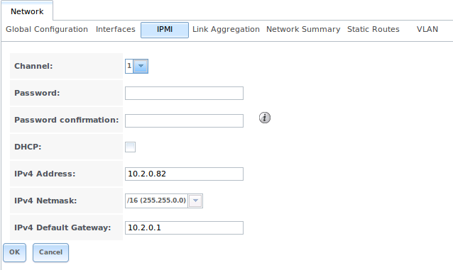
Table 7.4a: IPMI Options
| Setting | Value | Description |
|---|---|---|
| Password | string | input the password used to connect to the IPMI interface from a web browser |
| DHCP | checkbox | if left unchecked, the following three fields must be set |
| IPv4 Address | string | IP address used to connect to the IPMI web GUI |
| IPv4 Netmask | drop-down menu | subnet mask associated with the IP address |
| IPv4 Default Gateway | string | default gateway associated with the IP address |
Once configured, you can access the IPMI interface using a web browser and the IP address you specified in the configuration. The management interface will prompt for a username and the password that you configured. Refer to the documentation for the IPMI device to determine the default administrative username.
The default username is ADMIN (in all caps). Once you have logged into the management interface, you can change the administrative username as well as create additional users. The appearance of the utility and the functions that are available within the IPMI management utility will vary depending upon the hardware.
7.5. Link Aggregations
TrueNAS® uses FreeBSD’s lagg(4) interface to provide link aggregation and link failover. The lagg interface allows aggregation of multiple network interfaces into a single virtual lagg interface, providing fault-tolerance and high-speed multi-link throughput. The aggregation protocols supported by lagg determine which ports are used for outgoing traffic and whether a specific port accepts incoming traffic. The link state of the lagg interface is used to validate if the port is active or not.
Aggregation works best on switches supporting LACP, which distributes traffic bi-directionally while responding to failure of individual links. TrueNAS® also supports active/passive failover between pairs of links. The LACP, FEC and load-balance modes select the output interface using a hash that includes the Ethernet source and destination address, VLAN tag (if available), IP source and destination address, and flow label (IPv6 only). The benefit can only be observed when multiple clients are transferring files from your NAS. The flow entering into your NAS depends on the Ethernet switch load-balance algorithm.
The lagg driver currently supports the following aggregation protocols:
Failover: the default protocol. Sends traffic only through the active port. If the master port becomes unavailable, the next active port is used. The first interface added is the master port; any interfaces added after that are used as failover devices. By default, received traffic is only accepted when received through the active port. This constraint can be relaxed, which is useful for certain bridged network setups, by setting net.link.lagg.failover_rx_all to a non-zero value in System –> Sysctls –> Add Sysctl.
FEC: supports Cisco EtherChannel on older Cisco switches. This is a static setup and does not negotiate aggregation with the peer or exchange frames to monitor the link.
LACP: supports the IEEE 802.3ad Link Aggregation Control Protocol (LACP) and the Marker Protocol. LACP will negotiate a set of aggregable links with the peer into one or more link aggregated groups (LAGs). Each LAG is composed of ports of the same speed, set to full-duplex operation. The traffic will be balanced across the ports in the LAG with the greatest total speed; in most cases there will only be one LAG which contains all ports. In the event of changes in physical connectivity, link aggregation will quickly converge to a new configuration. LACP must be configured on the switch as well.
Load Balance: balances outgoing traffic across the active ports based on hashed protocol header information and accepts incoming traffic from any active port. This is a static setup and does not negotiate aggregation with the peer or exchange frames to monitor the link. The hash includes the Ethernet source and destination address, VLAN tag (if available), and IP source and destination address. Requires a switch which supports IEEE 802.3ad static link aggregation.
Round Robin: distributes outgoing traffic using a round-robin scheduler through all active ports and accepts incoming traffic from any active port. This mode can cause unordered packet arrival at the client. This has a side effect of limiting throughput as reordering packets can be CPU intensive on the client. Requires a switch which supports IEEE 802.3ad static link aggregation.
None: this protocol disables any traffic without disabling the lagg interface itself.
Note
the TrueNAS® system must be rebooted after configuring the lagg device and TCP access will be lost during reboot.
Do not configure the interfaces used in the lagg device before creating the lagg device.
7.5.1. Considerations When Using LACP, MPIO, NFS, or ESXi
LACP bonds Ethernet connections in order to improve bandwidth. For example, four physical interfaces can be used to create one mega interface. However, it cannot increase the bandwidth for a single conversation. It is designed to increase bandwidth when multiple clients are simultaneously accessing the same system.
LACP reads the sender and receiver IP addresses and, if they are deemed to belong to the same TCP connection, always sends the packet over the same interface to ensure that TCP does not need to reorder packets. This makes LACP ideal for load balancing many simultaneous TCP connections, but does nothing for increasing the speed over one TCP connection.
MPIO operates at the iSCSI protocol level. For example, if you create four IP addresses and there are four simultaneous TCP connections, MPIO will send the data over all available links. When configuring MPIO, make sure that the IP addresses on the interfaces are configured to be on separate subnets with non-overlapping netmasks or configure static routes to do point-to-point communication. Otherwise, all packets will pass through one interface.
LACP and other forms of link aggregation generally do not work well with virtualization solutions. In a virtualized environment, consider the use of iSCSI MPIO through the creation of an `iSCSI Portal`_. This allows an iSCSI initiator to recognize multiple links to a target, utilizing them for increased bandwidth or redundancy. This how-to contains instructions for configuring MPIO on ESXi.
NFS does not understand MPIO. Therefore, you will need one fast interface since creating an iSCSI portal will not improve bandwidth when using NFS. LACP does not work well to increase the bandwidth for point-to-point NFS (one server and one client). LACP is a good solution for link redundancy or for one server and many clients.
7.5.2. Creating a Link Aggregation
Before creating a link aggregation, double-check that no interfaces have been manually configured in Network –> Interfaces –> View Interfaces. If any configured interfaces exist, delete them as lagg creation will fail if any interfaces are manually configured.
Figure 7.5a shows the configuration options when adding a lagg interface using Network –> Link Aggregations –> Create Link Aggregation.
Figure 7.5a: Creating a lagg Interface

Select the desired aggregation protocol, highlight the interface(s) to associate with the lagg device, and click the OK button.
Once the lagg device has been created, it will be listed in the tree under an entry which indicates the type of protocol. It will also appear in “View Link Aggregations”. Click a link aggregation entry to see the buttons to edit that lagg interface, delete the link aggregation, or edit the lagg’s member interfaces.
After creating the lagg interface, set the IP address manually or with DHCP and save. The connection to the web interface may be lost at this point, and if so, the system must be rebooted from the console setup menu. You may also have to change your switch settings to communicate through the new lagg interface. After reboot, if the IP address was set manually, you may also have to manually enter a default gateway from the console setup menu option in order to get access into the GUI through the new lagg interface.
If you click the “Edit” button for a lagg, you can set the configuration options described in Table 7.5a.
Table 7.5a: Configurable Options for a lagg
| Setting | Value | Description |
|---|---|---|
| NIC | string | read-only as automatically assigned next available numeric ID |
| Interface Name | string | by default same as device (NIC) name, can be changed to a more descriptive value |
| DHCP | checkbox | check if the lagg device gets its IP address info from DHCP server |
| IPv4 Address | string | mandatory if DHCP is left unchecked |
| IPv4 Netmask | drop-down menu | mandatory if DHCP is left unchecked |
| Auto configure IPv6 | checkbox | check only if DHCP server available to provide IPv6 address info |
| IPv6 Address | string | optional |
| IPv6 Prefix Length | drop-down menu | required if input IPv6 address |
| Options | string | additional ifconfig(8) options |
This screen also allows you to configure an alias for the lagg interface. If you wish to set multiple aliases, click the “Add extra Alias” link for each alias you wish to configure.
If you click the “Edit Members” button, click the entry for a member, then click its “Edit” button, you can set the configuration options summarized in Table 7.5b.
Table 7.5b: Configuring a Member Interface
| Setting | Value | Description |
|---|---|---|
| LAGG Interface group | drop-down menu | select the member interface to configure |
| LAGG Priority Number | integer | order of selected interface within the lagg; configure a failover to set the master interface to 0 and the other interfaces to 1, 2, etc. |
| LAGG Physical NIC | drop-down menu | physical interface of the selected member |
| Options | string | additional parameters from ifconfig(8) |
Note
options can be set at either the lagg level (using the “Edit” button) or the individual parent interface level (using the “Edit Members” button). Typically, changes are made at the lagg level as each interface member will inherit from the lagg. If you instead configure the interface level, you will have to repeat the configuration for each interface within the lagg. However, some lagg options can only be set by editing the interface. For instance, the MTU of a lagg is inherited from the interface. To set an MTU on a lagg, set all the interfaces to the same MTU.
To see if the link aggregation is load balancing properly, run the following command from `Shell`_:
systat -ifstat
More information about this command can be found at systat(1).
7.6. Network Summary
Network –> Network Summary allows you to quickly view the addressing information of every configured interface. For each interface name, the configured IP address(es), DNS server(s), and default gateway will be displayed.
7.7. Static Routes
By default, no static routes are defined on the TrueNAS® system. Should you need a static route to reach portions of your network, add the route using Network –> Static Routes –> Add Static Route, shown in Figure 7.7a.
Figure 7.7a: Adding a Static Route
The available options are summarized in Table 7.7a.
Table 7.7a: Static Route Options
| Setting | Value | Description |
|---|---|---|
| Destination network | integer | use the format A.B.C.D/E where E is the CIDR mask |
| Gateway | integer | input the IP address of the gateway |
| Description | string | optional |
If you add any static routes, they will show in “View Static Routes”. Click a route’s entry to access its “Edit” and “Delete” buttons.
7.8. VLANs
TrueNAS® uses FreeBSD’s vlan(4) interface to demultiplex frames with IEEE 802.1q tags. This allows nodes on different VLANs to communicate through a layer 3 switch or router. A vlan interface must be assigned a parent interface and a numeric VLAN tag. A single parent can be assigned to multiple vlan interfaces provided they have different tags. If you click Network –> VLANs –> Add VLAN, you will see the screen shown in Figure 7.8a.
Note
VLAN tagging is the only 802.1q feature that is implemented.
Figure 7.8a: Adding a VLAN
Table 7.8a summarizes the configurable fields.
Table 7.8a: Adding a VLAN
| Setting | Value | Description |
|---|---|---|
| Virtual Interface | string | use the format vlanX where X is a number representing the vlan interface |
| Parent Interface | drop-down menu | usually an Ethernet card connected to a properly configured switch port; if using a newly created lagg device, it will not appear in the drop-down until the system is rebooted |
| VLAN Tag | integer | should match a numeric tag set up in the switched network |
| Description | string | optional |
The parent interface of a vlan has to be up, but it can have an IP address or it can be unconfigured, depending upon the requirements of the VLAN configuration. This makes it difficult for the GUI to do the right thing without trampling the configuration. To remedy this, after adding the VLAN, go to Network –> Interfaces –> Add Interface. Select the parent interface from the NIC drop-down menu and in the “Options” field, type up. This will bring up the parent interface. If an IP address is required, it can be configured using the rest of the options in the “Add Interface” screen.
